
RIMET KNOWLEDGE BASE – 24.10.2025
RIMET KNOWLEDGE BASE – 24.10.2025
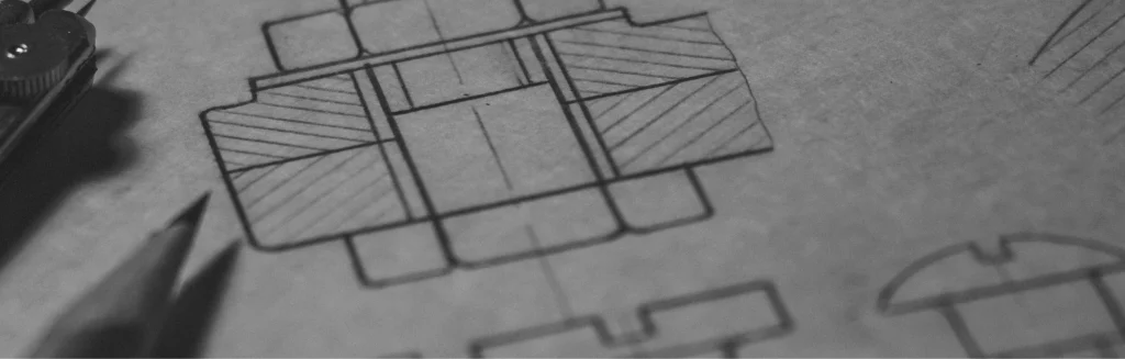
A technical drawing is the key document that determines whether a part will be manufactured correctly on a CNC mill or lathe. It defines the geometry, dimensions, tolerances and surface quality requirements. Whether created in a CAD environment or as a simple 2D drawing, its clarity and completeness have a direct impact on pricing, lead time and production quality.
At RIMET, we work daily with numerous customer projects from various industries. Below are practical guidelines that help avoid misunderstandings and speed up both quotation and production.
A good drawing must be clear, unambiguous and complete. The less room for interpretation, the lower the risk of error.
Clear, non-overlapping views
All critical dimensions
Tolerances
Surface requirements
Isometric view
Not required, but very helpful for understanding the geometry.
Material specification
Examples:
• EN AW-6061,
• stainless steel 1.4301,
• PA6 black.
Legend and units
Most commonly: all dimensions in mm.
The most universal formats are:
• PDF – for reading and interpreting dimensions,
• STEP/STP – for verifying 3D geometry and preparing machining strategies.
PDF ensures unambiguous dimensions, while the STEP file helps detect geometric issues early.
We also work with 2D drawings, but converting them into a 3D model may extend the quotation process.
Not perfect, but clear and complete.
The most common documentation issues include:
• missing tolerances,
• missing material information,
• unclear hole depths,
• conflicting dimensions,
• hand-drawn sketches without scale.
Any unclear element means additional questions, which prolongs the quotation stage.
At RIMET, we always verify the drawing before starting production.
Lower risk of errors
Even a single imprecise dimension can invalidate an entire batch.
Faster quotation and production
Complete documentation means fewer questions and quicker technological preparation.
Higher repeatability
Clear drawings help reproduce the part accurately every time.
Many customers provide:
• scans,
• hand sketches,
• photos of workshop drawings.
We can work with them, but converting such materials into CAD or PDF:
• takes time,
• may introduce errors,
• increases preparation cost.
This ensures that your documentation and production remain consistent from start to finish.